
Laboratory application
FLEC laboratory setup for controlled VOC emission testing
A typical laboratory system combines controlled clean air, the FLEC Air Control 1000, the FLEC Cell, an optional FLEC Sub-Unit for non-flat or separate samples, suitable sampling tubes and calibrated low-flow pumps.
System overview
Typical FLEC laboratory configuration
The exact sampling medium and analytical method depend on the target compounds. The flow path below shows the core arrangement used to supply conditioned air to the test surface and collect emitted compounds.
Clean, dry supply air
External synthetic or otherwise suitable clean compressed air.

FLEC Air Control 1000
Regulates air flow, humidity and purity before the air enters the FLEC Cell.
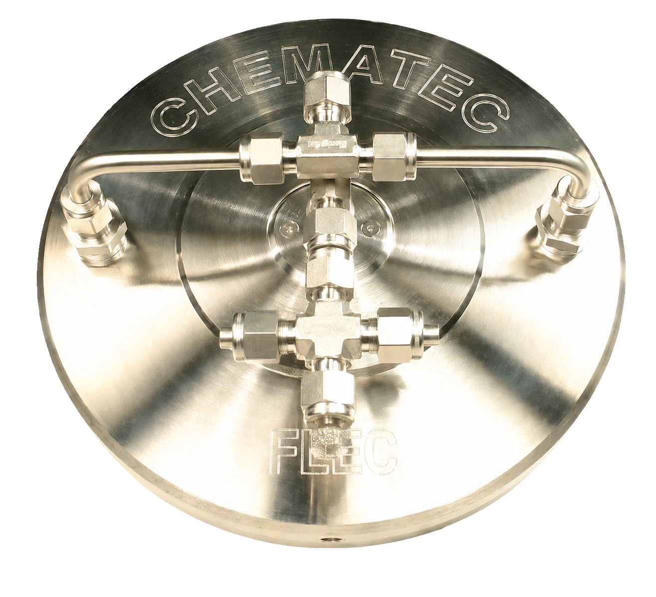
FLEC Cell and specimen
The cell defines the exposed surface area and carries released compounds to the outlets.
Sampling tubes and pumps
One or two suitable tubes connected to calibrated low-flow sampling pumps.
What a complete laboratory setup includes
- FL-0001 FLEC Cell with clean O-ring and suitable support or test plate
- FL-1000 FLEC Air Control 1000 or another documented source of controlled clean and humidified air
- Optional FL-2001 or FL-2002 FLEC Sub-Unit for non-planar, porous, liquid, sticky or separate specimens
- Clean tubing and fittings compatible with the selected measurement method
- One or two sampling tubes selected for the target compounds
- Calibrated low-flow pumps and independent flow verification
- A prepared material specimen, recorded environmental conditions and a documented sampling plan
Laboratory measurement sequence
- Define the material, target compounds, method and required conditioning period.
- Clean and prepare the FLEC Cell, O-ring, tubing and specimen support.
- Connect the clean-air supply to the FLEC Air Control and set the required flow and relative humidity.
- Position and seal the FLEC Cell directly on a flat specimen, or fit it to the selected FLEC Sub-Unit, without contaminating the measurement surface.
- Connect the selected sampling tubes and calibrated pumps, then verify inlet and sampling flows.
- Collect the samples for the documented period and analyse them using the selected VOC or carbonyl method.
Maintain a positive air balance
The total sampling flow should remain below the inlet flow so a small excess can leave through the FLEC vent. This helps limit entry of surrounding laboratory air. Record both inlet and outlet flows and follow the acceptance criteria in the applicable method.
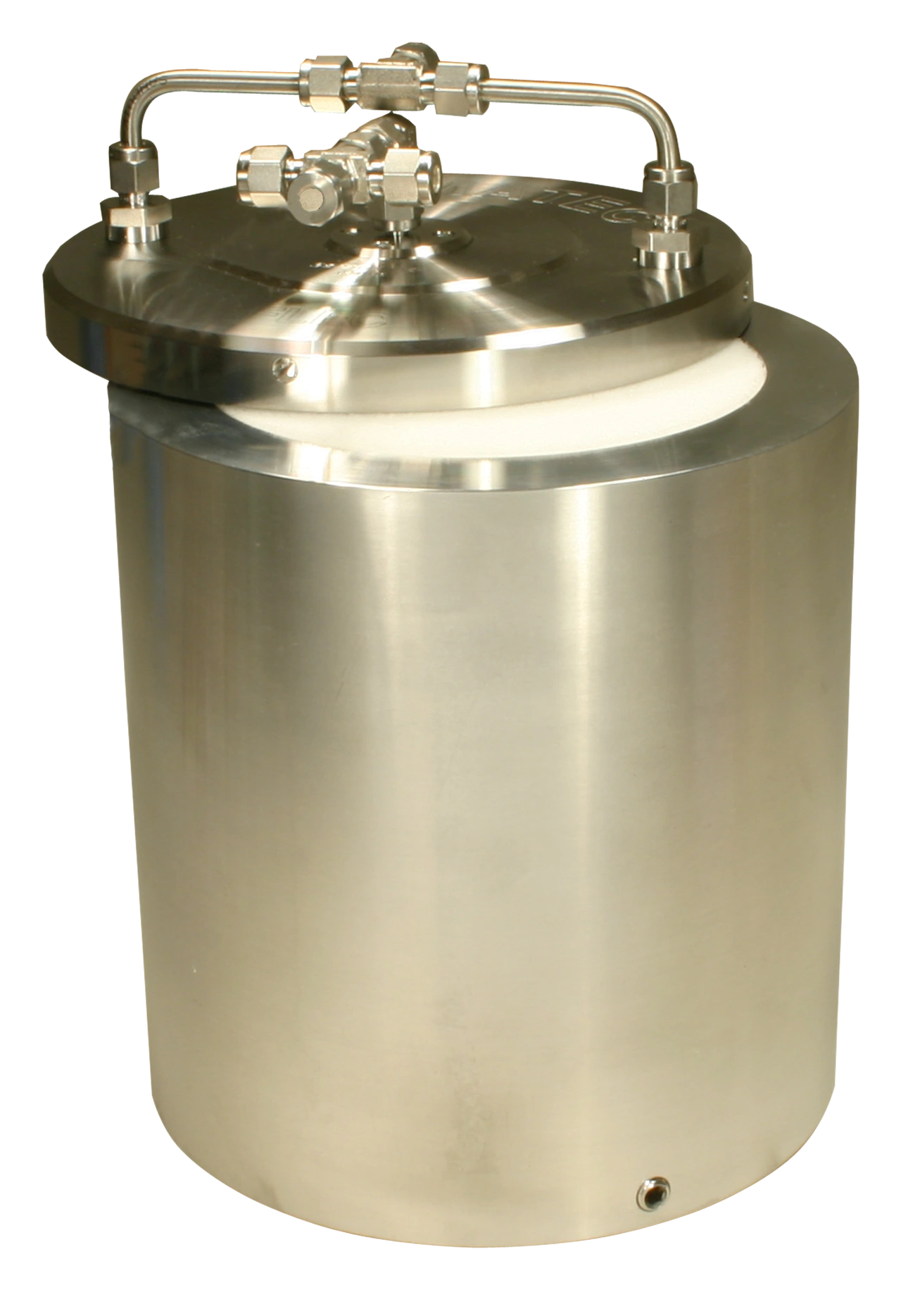
Optional sample holder
Add a FLEC Sub-Unit for non-flat or separate samples
Use a FLEC Sub-Unit when the specimen cannot be tested as a flat surface directly beneath the FLEC Cell. The adjustable chamber supports non-planar, porous, liquid or sticky materials while exposing only the upper sample surface.
- FL-2001: 150 mm internal diameter and adjustable chamber height from 0 to 100 mm.
- FL-2002: 152 mm internal diameter, suitable for a standard Petri dish, with adjustable chamber height from 0 to 100 mm.
Standards and method selection
FLEC laboratory measurements are covered by established material-emission methods including ISO 16000-10, ASTM D7143-24 and NT BUILD 438. Supporting sampling and analytical procedures are described in relevant parts of the ISO 16000 and ISO 16017 series. See the FLEC standards overview.